UTXvL: Universal overcurrent, earth overcurrent protection relay
UTXvL protection is intended for protecting CB Bays which operate with earthed neutral point in any configuration.
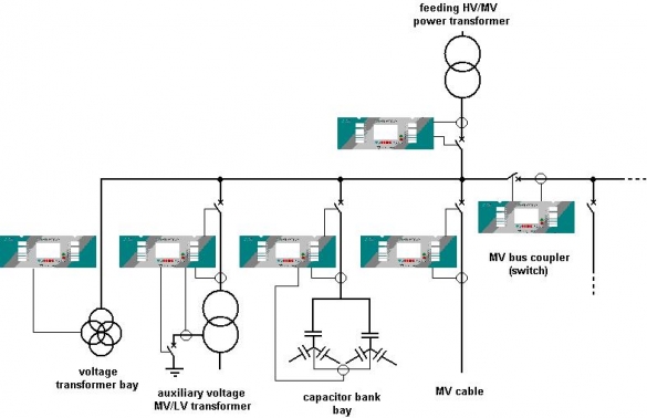
It provides quick and effective CB tripping while any: PTP or PTG fault will be detected. Reliable operation of the device is based on precise and quick analog value measurements, resulting in fast (voltages, currents, Earth Fault Admittance) vectors finding. UTXvL is equipped with: 14 Bit A/C converters, serial transmission interfaces (RS 232 – supervising channel and RS 485 – using IEC 870-5-103 standard protocol), with optional optical fibre and/or network communication – TCP/IP. Individually configured UTXvL relay is intended for protecting CB Bays (Overhead Line/ Underground Cable, Feeding HV/MV Power Transformer, Auxiliary Voltage MV/LV Transformer, MV Bus Coupler, Capacitor Bank).
Device characteristics
UTXvL characteristics:
- multi-processor digital measuring and decision-making system equipped with 5 groups of protection settings
- galvanically insulated inputs and outputs (analog and digital)
- four overcurrent measuring stages for each phase: directional or non-directional (4 x I>)
- two phase overvoltage stages (2 x U>)
- two phase undervoltage stages (2 x U<) 32 – one reverse active overpower stage (P>)
- one reactive power stage (Q<>, tg<>) for compensation purposes
- three: independent, non-directional earth fault overcurrent stages (3 x IE > T)
- three residual overvoltage (neutral displacement) stages (3 x UE > T)
- two sensitive earth fault overcurrent stages (2x Iedir.>T)
- one sensitive earth fault admittance stage (RYe, RBe, Rge)
- one sensitive earth fault admittance differential stage (RYYe)
- two non-directional overcurrent stages – for internal faults (2 x Iy > T)
- negative sequence overcurrent and overvoltage protections
- second harmonic phase current compound detector
- simplified overcurrent substation bus protection function
- freely programmable substation circuit breaker failure protection function
- four internal Underfrequency Load Shedding and two AR after Underfrequency Load Shedding stages (4 x LS + 2 x ARLS)
- four external Underfrequency Load Shedding and AR after Underfrequency Load Shedding stages (4 x LS + 4 x ARLS)
- neutral point – automatic resistance insertion logic
- capacitor bank automatic switching logic
- four shot, six mode, three pole AR cycle for any protective or logic function
- bay failure or trip/relay internal trouble signalling: UP, AL, AW (three standard substation busses)
- fully programmable digital inputs for signals from external protection relays
- CB switching onto fault (SOTF) protection logic
- LCD bay terminal screen, displaying actual (CB, bus and line reclosers, earthing switches) status
- each protection stage can be set as signal operating only (operational report)
- analog signal vector stabilization and compensation (due to unstable fault evolving) for precise and selective fault detection
- permanent monitoring of bay internal element operational status/ condition
- three-level password protection
- event and disturbance recording (4 x U; 4 x I; 16 x digital signals)
- analog signal synchro-sampling and external clock synchronization
- permanent monitoring of CB opertaional ciruits (1 x ON; 2 x OFF)
- CB internal operational status (ready/ failure) monitoring and remote control
- analog signal/ value (I, U, S, P, Q, f, Ep, Eq) front panel (local) visualisation and remote data transfer
- CB currents tripping cumulative function, number of operations and protection relay operating time
- detailed fault monitoring, for local/remote fault clearance evaluation
- graphic LCD display, 11-key keypad and 16 LEDs (15 freely programmable)
- four quadrant energy counters
- 32 logic functions with programmable modifiers for realization of simple and complex algorithms.
- possibility of visualization, control and configuration by SAZ 2000 program
- possibility of cooperation with Automatic Over Ethernet (AoE) systems and with Alice`79 system.


